Lennart Hinz, Sebastian Metzner, Philipp Müller, Robert Schulte, Hans-Bernward Besserer, Steffen Wackenrohr, Christopher Sauer, Markus Kästner, Tino Hausotte, Sven Hübner, Florian Nürnberger, Benjamin Schleich, Bernd-Arno Behrens, Sandro Wartzack, Marion Merklein, Eduard Reithmeier (2021); Sensors, Volume 21, Ausgabe 7, Seite 2389
Dimensional accuracy
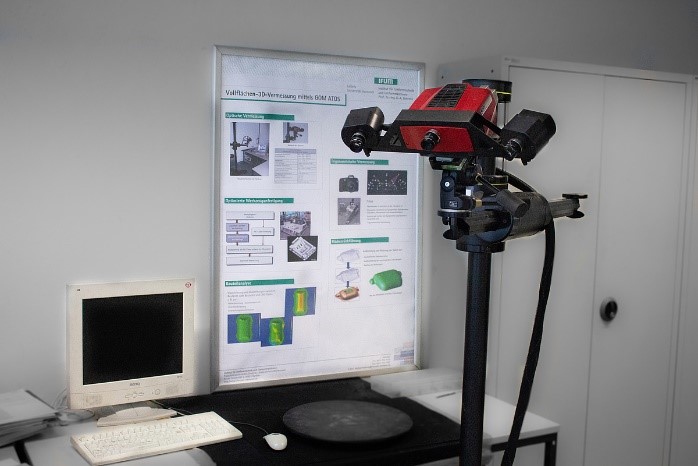
Knowledge of the exact tool geometry of series tools is of particular importance for the dimensional accuracy of the sheet metal parts to be manufactured. The development of photogrammetric measuring systems facilitates the assessment of sheet metal parts with regard to their geometric shape accuracy and shape change distribution. For this purpose, the components are scanned with the IFUM's GOM- Atos 2 400, for example, and a 3D model of the components is created.


Subsequently, the scanned 3D model of the components can be superimposed on the existing CAD data of the tool. By means of this method, the dimensional accuracy of the component can be verified. Furthermore, a comparison with the predicted simulation results usually takes place in order to optimise the simulation accuracy. Fast and precise measurements of large-scale drawn part and die surfaces are guaranteed. Thus, an automatic measurement independent of the test person can be guaranteed.
Forming analysis
The forming analysis is intended to increase the understanding of the process. For example, component geometry, material selection and forming temperature can have a major impact on the springback of the component. Furthermore, the determination of local deformation in sheet metal forming, especially for parts close to the process boundary, is of particular importance in order to ensure a reproducible manufacturing process. At IFUM, the optical forming analysis system GOM-Argus is used for this purpose, which ensures an evaluation of forming processes and forming simulation.
Surfaces
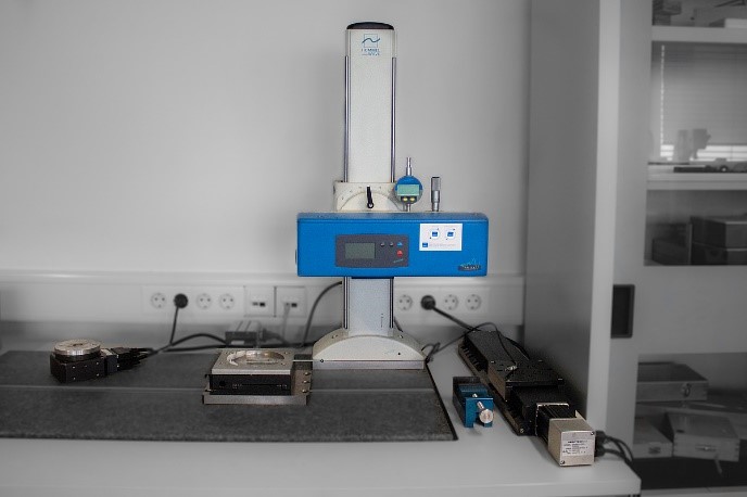
In addition to optical metrology, tactile measurements are performed precisely on drawn parts and forming tools. By means of the characterisation of the tool or component surfaces, a multitude of process influences can be investigated. The analysis of the surfaces enables conclusions to be drawn about tool wear, the optimum forming force and the selection of suitable lubricants. The T8000-RC surface measuring station from Jenoptik/HOMMEL-ETAMIC enables individual applications and combined measurements in the areas of contour measurement, roughness measurement and topography measurement. A levelling air damping table with stone plate complements the tactile measurement system.


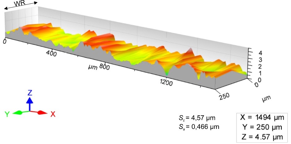
The surface roughness of metallic components, for example, also allows conclusions to be drawn about the adhesive behaviour of plastics on metal surfaces. This is particularly important for the production of hybrid components. In addition to individual measurement sections, several measurement sections can also be run next to each other during the analysis. Software is then used to generate the 3D surfaces of the measuring sections from this data and to determine the maxima Sz and the mean surface roughness Sa.


Another method of measuring the surface is offered by the optical method using the Keyence VR-3200 profilometer. This is non-contact and enables faster measurements of surfaces compared to the tactile measurement method.


PUBLICATION
Fringe projection profilometry in combination with other optical measuring technologies has established itself over the last decades as an essential complement to conventional, tactile measuring devices. The non-contact, holistic reconstruction of complex geometries within fractions of a second in conjunction with the lightweight and transportable sensor design open up many fields of application in production metrology. Furthermore, triangulation-based measuring principles feature good scalability, which has led to 3D scanners for various scale ranges. Innovative and modern production processes, such as sheet-bulk metal forming, thus, utilize fringe projection profilometry in many respects to monitor the process, quantify possible wear and improve production technology. Therefore, it is essential to identify the appropriate 3D scanner for each application and to properly evaluate the acquired data. Through precise knowledge of the measurement volume and the relative uncertainty with respect to the specimen and scanner position, adapted measurement strategies and integrated production concepts can be realized. Although there are extensive industrial standards and guidelines for the quantification of sensor performance, evaluation and tolerancing is mainly global and can, therefore, neither provide assistance in the correct, application-specific positioning and alignment of the sensor nor reflect the local characteristics within the measuring volume. Therefore, this article compares fringe projection systems across various scale ranges by positioning and scanning a calibrated sphere in a high resolution grid.


